KLST_TINY-v0.1 Prototype in Production
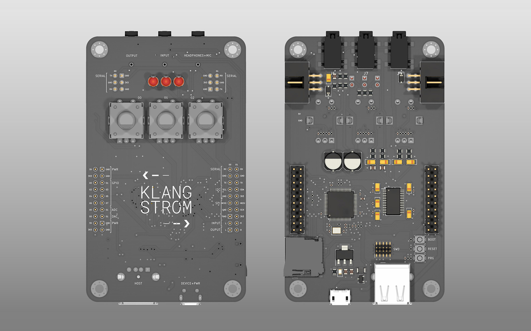
after 5 days of hard work the first release of the KLST_TINY is done and sent off for production.
although it might not look like it, the board design has evolved quite a lot in the last days. however, the feature list remained quite stable:
Feature List (20210322)
- STM32F446 MCU with 180MHz, 128KB RAM, 512KB Flash
- WM8731 Audio Codec with 2× AUDIO DAC + 2× AUDIO ADC ( 24BIT )
- 2× ADC ( 12BIT, opt 6 extra channels )
- 2× DAC ( 12BIT )
- 8× GPIO
- 2× UART ( serial )
- 1× USB ( USB device + client connector)
- 1× I2C
- 1× SPI
- 3× Rotary Encoders with Buttons ( TIM2, TIM3, TIM8 )
- 3× programmable LEDs + 1× Power LED
- 11× TIMERS
- 1× SD CARD READER
- 1× JTAG/SWD Interface ( 10-Pin )
- Reset + Boot Flash + Programmer Buttons
- 4× Mounting Holes
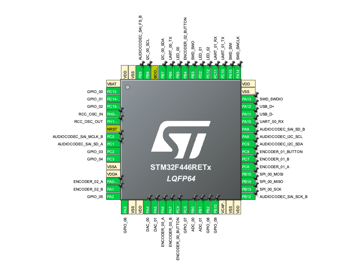
STM32F446RET Pin Assignments
Design Decisions
Physical Interface
the interface consists of programmable 3 LEDs and 3 rotary encoders with push buttons. this is quite a reduced set of elements. however i think that it allows for quite a lot of interactions ( see one-button interfaces ).
it would be quite interesting to see how much one can squeeze out of these minimal input ( rotation and push ) and outputs ( lights ) …
however, if a more complex interaction is required the boards features the common interfaces to extend the interactions with external components.
Hardware Interfaces
the board can be interfaced via the GPIOs and the ADCs with common sensors ( e.g buttons or slider potentiometers ) and via the I2C and SPI ports with more complex components ( e.g LED screens ). on the back of the board a SD card connector is located which allows to read and write micro SD cards via the SPI interface.
special attention was given to the serial ports. in contrast to the other front facing interfaces the two serial ports are also located on the backside of the board. via Insulation-Displacement Contact connectors (IDC) ( i.e flat ribbon cables ) the board can be connected to other KLST_TINY boards.
the board comes with a single USB interface. it can either run as a client ( e.g receive virtual MIDI events ) or a host ( e.g read keystrokes of a keyboard ) device. it is fitted with a USB-B-micro client connector ( which should also be used to power the board ) and a USB-A host connector.
and lastly the board can send and receive audio signals via the line-in and line-out 3.5mm stereo audio connectors, or via the integrated headphone+mic 3.5mm audio connector. the latter can be used with a common headset which usually consists of a stereo output ( headphone ) and mono input ( microphone ).
Audio Codec
while KLST_CORE uses the native I2S interface of the STM32H746 MCU the KLST_TINY board now communicates via Serial Audio Interface (SAI) emulating the I2S protocoll. while this is not relevant for the use of the board it might be interesting to the technically inclined ;)
the reason to switch from I2S to SAI is that the STM32F466 does not offer full-duplex mode ( simultaneous input + output ) via I2S.
the audio codec will run at 48KHz with a resolution of 24-bit.
Programming
the KLST_TINY board can be programmed in two different ways. either via USB in Device Firmware Upgrade (DFU) mode or via the JTAG/SWD connector. the disadvantage of the latter approach is that it requires an external in-circuit debugger and programmer ( e.g ST-LINK ), the advantage however is that it allows advanced debugging features.
Add-ons ( an Outlook )
the KLST_TINY board, however note exclusively, aims to allow the development of mobile musical instruments. for this purpose two add-ons are more or less required or at least helpful: a power supply and an external speaker.
a mobile power supply can be simply facilitated by connecting the board to a standard USB power bank. however, a dedicated power supply that fits the form factor more nicely would be great.
an external speaker that can be easily connected to the device would be a useful extension to the board. the speaker could be mounted directly onto a dedicated PCB that would also hold an amplifier circuit.