IDC Serial Cables
IDC serial cables for KLST_SHEEP boards are terminated with a 6-pin socket connector on each side. each KLST_SHEEP board is fitted with 2 IDC connectors with shrouded headers.
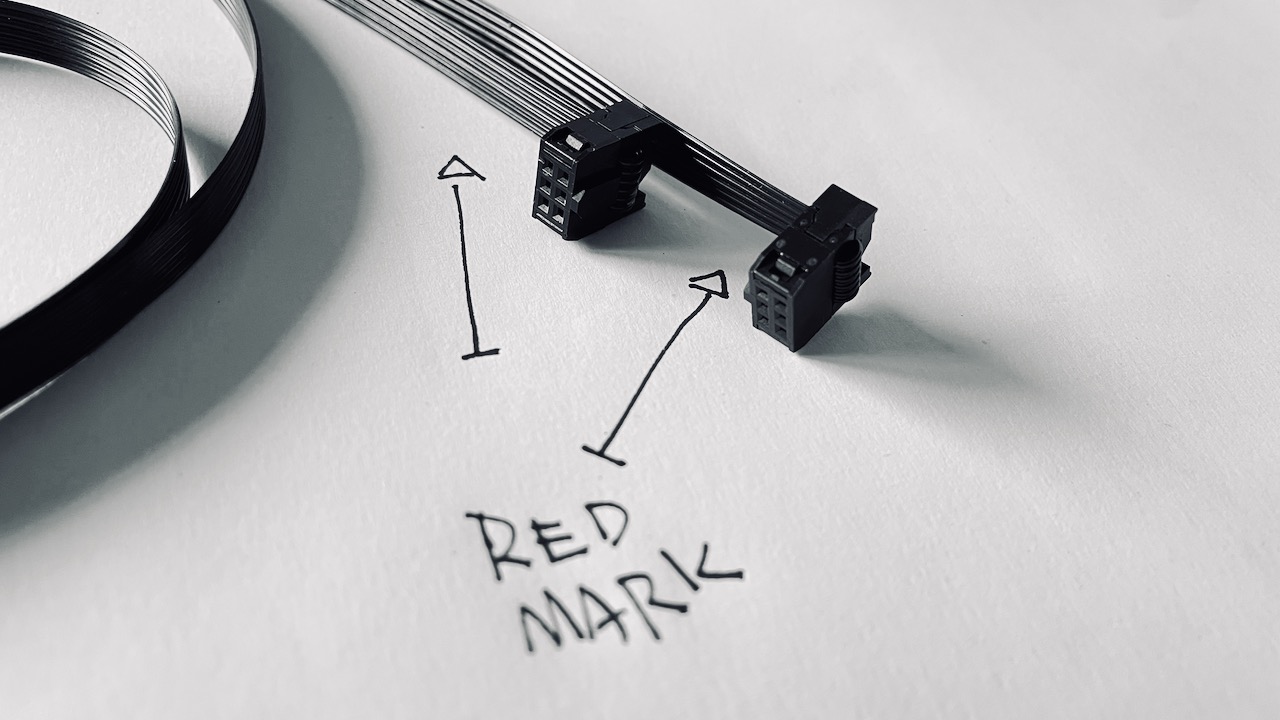
IDC serial cables are assembled with one normal and one rotated1 socket connector. this results into the following cable pin assignment ( looking into the cable sockets ):
      NORMAL                ROTATED
      +-----+               +-----+
+-----+-----+-----+   +-----+-----+-----+
|  6  |  4  |  2  |   |  5  |  3  |  1  |
| GND | 3V3 | TX  |   | RX  | 3V3 | GND |
+-----+-----+-----+   +-----+-----+-----+
|  5  |  3  |  1  |   |  6  |  4  |  2  |
| RX  | 3V3 | GND |   | GND | 3V3 | TX  |
+-----------------+   +-----------------+
such a twisted cable connects the transmit pin ( TX ) of one connector with the receive pin ( RX ) of another connector. this allows for serial communication between devices.
3V3 + GND pins are arranged symetrically and do not change behavior.
for the sake of completes follows a pin assignment for the sockets mounted on the boards ( looking into the shrouded header connector ):
      +-----+
+-----+-----+-----+
|  2  |  4  |  6  |
| TX  | 3V3 | GND |
+-----+-----+-----+
|  1  |  3  |  5  |
| GND | 3V3 | RX  |
+-----------------+
-
normal in this context means that the connector is crimped onto the flat ribbon cable aligning the arrow ( on the connector ) and the first outer wire of the cable ( usually marked with a red stripe on a grey flat-ribbon cable ). rotated means that the arrow is crimped on to last outer wire ( opposite of the red stripe ). ↩