KLST_PANDA Prototyping
i will start the prototyping with ST’s development board NUCLEO-H723ZG. it allows to test most ( not all ) features and peripherals. PS { the boards connectors need to be equipped with double-row pin headers first … grrrmpf }
i am still struggling with one fundamental decision and that is whether i should produce smaller PCBs ( e.g for external memory BGA-24 IC ) and test them individually or if i should just take a leap of faith and design the entire board, planning 1–2 revision rounds. hmmm, difficult …
these are the sections or modules i want to test:
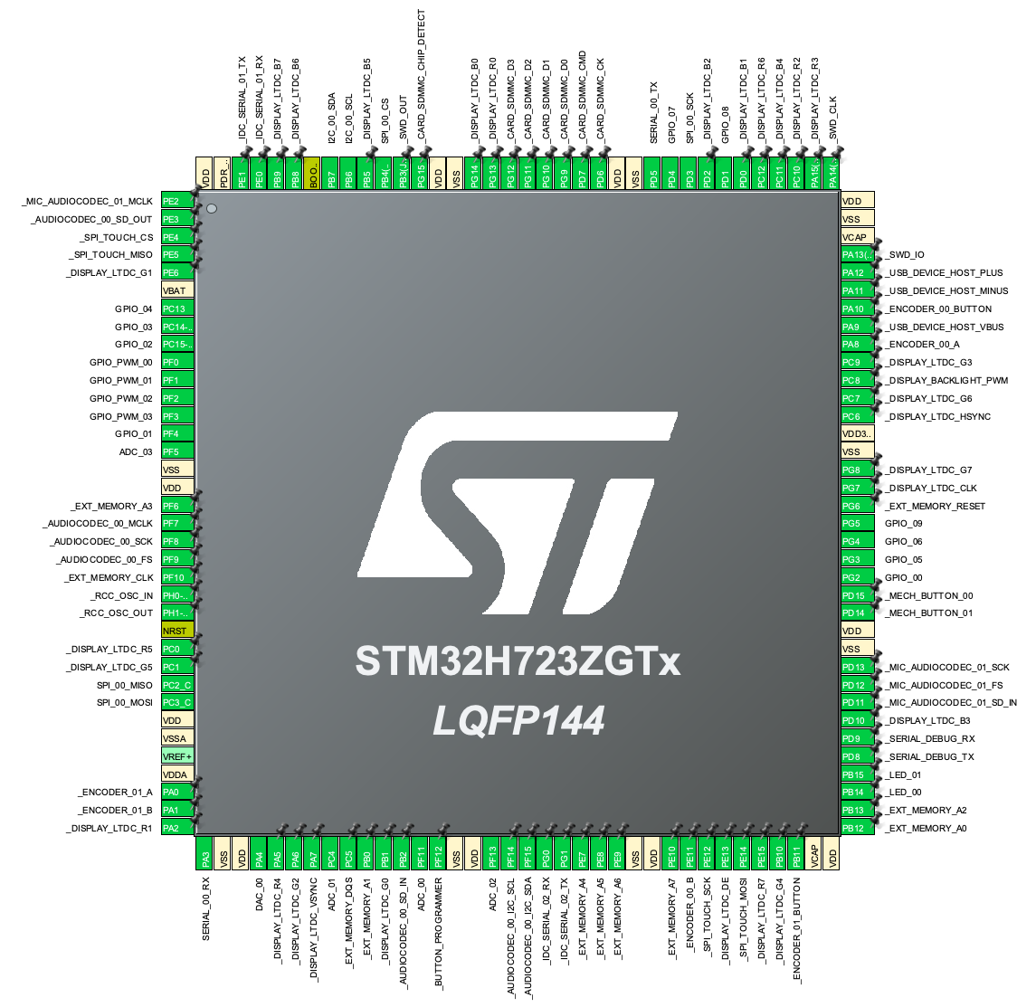
MCU
- STM32H723ZGT
display
- 4.3” 480×272
- capacitive touch interface (ADS7843)
- LTDC interface ( parallel )
- dimming backlight (FAN5333) with PWM + 40-pin TFT Friend - FPC Breakout with LED Backlight Driver
- parallel LTDC interface ( is external memory required? )
- decide ( and order ) displays (13×) ( see research.KLST_PANDA–TFTs.md )
external memory
- BGA-24 memory (APS12808L-3OBM-BA)
- Octo-SPI/HyperRAM™ interface
- not sure how to test the BGA-24 memory IC? to just have this manufactured as a PCB seems a bit excessive
battery + power supply
- test charging circuit (TP5400)
- with Lolin D1 Mini Battery Shield
- test with battery type 18650
- can the circuit charge and supply power simultanously?
- do we need a hardware on/off-switch? or can this also be done in software?
- with PCB mounted holder e.g MY-18650-01
on/off switch
“just thought that when we have a battery on board there might be the need to be able to switch the power supply on or off”
USB-C
- are 2× USB-C connectors required or would a single one work?
- one for charging or power supply
- … and one for USB Device/Host where it could also power the board when connected as a USB Device
audio codec
- test audio codec (WM8904)
- with PIC32 AUDIO CODEC DAUGHTER CARD (AC328904)
SDCard
- test 4-bit wide
SDIO/SDMMCinterface - test card detect functionality
ADC+DAC
- DAC(1×)+ADC(3×)
- connection to modular synth?!?
- 12V tolerant ( or modular connection as extension board = 0.0—3.3V > -12.0–12.0V + -1.0–1.0V>-5.0>5.0V(?) )
microphone
- test MEMS microphone ( via I2S )
- with Adafruit I2S MEMS Microphone Breakout - SPH0645LM4H
- e.g GMA4030H11-F26
GPIO
- what layout?
- maybe case with fake shrouded connectors ( see IDC housing )
- only 2 LEDs ( with PWM )
buttons
- reset, boot, programmer
mechanical keyboard keys
- 2×
- just below encoders?
programmer interface
- STD14
- pogo pin connector ( without housing on front-side )
case + shape
- switch?
- portrait mode?
- something unique!!!
- hole for a strap
- black&white PCB