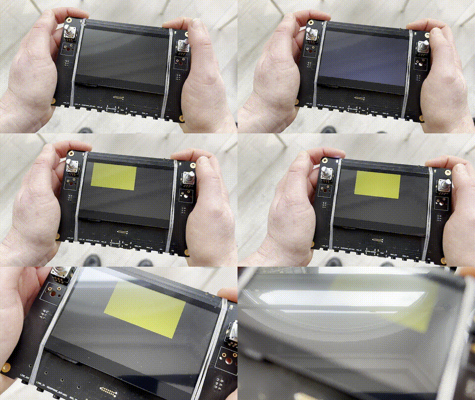
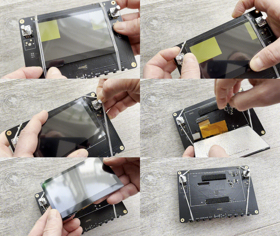
KLST_PANDA + Display

KLST_PANDA features ER-TFT043A2-3 ( with ST7282 TFT-LCD SOC Driver interfaced via LTDC ) a 4.3” TFT LCD with a resolution of 480×272px, a capacitive touch panel via controller FT5206 ( via I2C ) and a dimmable ( via PWM ) backlight driver CAT4139TD-GT3.
the display is interfaced via the on-board LTDC driver with a parallel 24-bit interface and connected to the board via a 40-pin FPC connector.

Configuring LTDC
the ST7282 datasheet in section 10.1.1 (p60) suggests the following typical timing configurations:
| ITEM | VALUE | Unit |
|---|---|---|
| DCLK Frequency | 9 | MHz |
| HSYNC | ||
| - Period Time | 531 | DCLK |
| - Display Period | 480 | DCLK |
| - Back Porch | 43 | DCLK |
| - Front Porch | 8 | DCLK |
| - Pulse Width | 4 | DCLK |
| VSYNC | ||
| - Period Time | 292 | H |
| - Display Period | 272 | H |
| - Back Porch | 12 | H |
| - Front Porch | 8 | H |
| - Pulse Width | 4 | H |
( H is equal to Line )
the LTDC clock is configured to run at approx 9.5MHz to achieve a framerate of 60Hz:
LTDC Clock Rate ( in MHz )
= TotalWidth * TotalHeight * RefreshRate / 1000000
= 534px * 295px * 60Hz / 1000000
= 9.45MHz
==@note( when adding the values above into STM32CubeIDE in the LTDC configuration the computed total width and height ( Total Width: 534 + Total Height: 295 ) differ from the proposed values Period Time above by 3. this would e.g result in a different LTDC clock rate of 9.3MHz. )==
Double Buffering and Memory Requirement
the firmware implements a double buffering technique. the current buffer can be switched with a function that may look like this:
#define FRAMEBUFFER1 0
#define FRAMEBUFFER2 1
#define FRAMEBUFFER1_ADDR (DISPLAY_FRAMEBUFFER_ADDRESS)
#define FRAMEBUFFER2_ADDR (DISPLAY_FRAMEBUFFER_ADDRESS + DISPLAY_FRAMEBUFFER_SIZE)
uint8_t active = FRAMEBUFFER1;

void LTDC_switch_framebuffer() {
	if (active == FRAMEBUFFER1) {
		LTDC_Layer1->CFBAR = FRAMEBUFFER2_ADDR;
		active = FRAMEBUFFER2;
	} else {
		LTDC_Layer1->CFBAR = FRAMEBUFFER1_ADDR;
		active = FRAMEBUFFER1;
	}
	LTDC->SRCR = LTDC_SRCR_VBR;
}

__IO uint32_t LTDC_get_backbuffer_address(void) {
	if (active_framebuffer == FRAMEBUFFER1)
		return (__IO uint32_t) FRAMEBUFFER2_ADDR;
	else
		return (__IO uint32_t) FRAMEBUFFER1_ADDR;
}
the two buffers required for double buffering consume approx 1MB of external memory ( 480px*272px*4*2=1044480=1020KB=0.996MB ).
@sidenote( the remaining 15MB allow approx 81.92sec ( =15*1024*1024/(48000*4) ) of 32-bit sample data ( 32-bit float ) at 48KHz sampling rate )
==@todo(optimize LTDC/DMA2D performance as suggested in 4.5 Graphic performance optimization (p46))==
DMA2D for Accelerated Drawing
additionally, the DMA2D feature can be used to accelerate transfer of rectangles ( R2M, register to memory ) and bitmaps ( M2M, memory to memory ).
a DMA2D transfer can be initiated with the HAL function HAL_DMA2D_Start(DMA2D_HandleTypeDef *hdma2d, uint32_t pdata, uint32_t DstAddress, uint32_t Width, uint32_t Height).
a function to fill a rectangular region with a single 32-bit color ( stored in a register in ARGB color format ) may look like this:
void DMA2D_FillRect(uint32_t color, uint32_t x, uint32_t y, uint32_t width, uint32_t height) {
	hdma2d.Instance = DMA2D;
	hdma2d.Init.Mode = DMA2D_R2M;
	hdma2d.Init.ColorMode = DMA2D_OUTPUT_ARGB8888;
	hdma2d.Init.OutputOffset = DISPLAY_WIDTH - width;
	HAL_DMA2D_Init(&hdma2d);
	HAL_DMA2D_ConfigLayer(&hdma2d, 0);
	HAL_DMA2D_ConfigLayer(&hdma2d, 1); // @TODO(investigate the roles of `HAL_DMA2D_ConfigLayer(&hdma2d, ...);`
	HAL_DMA2D_Start(&hdma2d,
	                color,
	                LTDC_get_backbuffer_address() + (x + y * DISPLAY_WIDTH) * 4,
	                width,
	                height);
	HAL_DMA2D_PollForTransfer(&hdma2d, 10); // @TODO(investigate the role of `HAL_DMA2D_PollForTransfer(DMA2D_HandleTypeDef, uint32_t)`)
}
Syncing to Vertical Blanking
a reload of the LTDC configuration at the next vertical blanking (VBLANK) can be scheduled with HAL_LTDC_Reload(&hltdc, LTDC_RELOAD_VERTICAL_BLANKING). on completion a callback is trigger at HAL_LTDC_ReloadEventCallback(LTDC_HandleTypeDef). this mechanism can be used to sync redrawing of display content to the display refresh rate of 60Hz.
Configuring Touch Screen Driver
the capacitive touch panel is intaced with the controller FT5206 via I2C ( I2C4 ) as well as a GPIO capable of generating an interrupt on touch on timer TIM4_CH2.
the touch driver is widely used and the communication with quite simple.
Backlight
the backlight of the display is driven by an CAT4139TD-GT3 IC. the brightness is controlled via a PWM driven GPIO pin on timer TIM3.