KLST_PANDA + MIDI
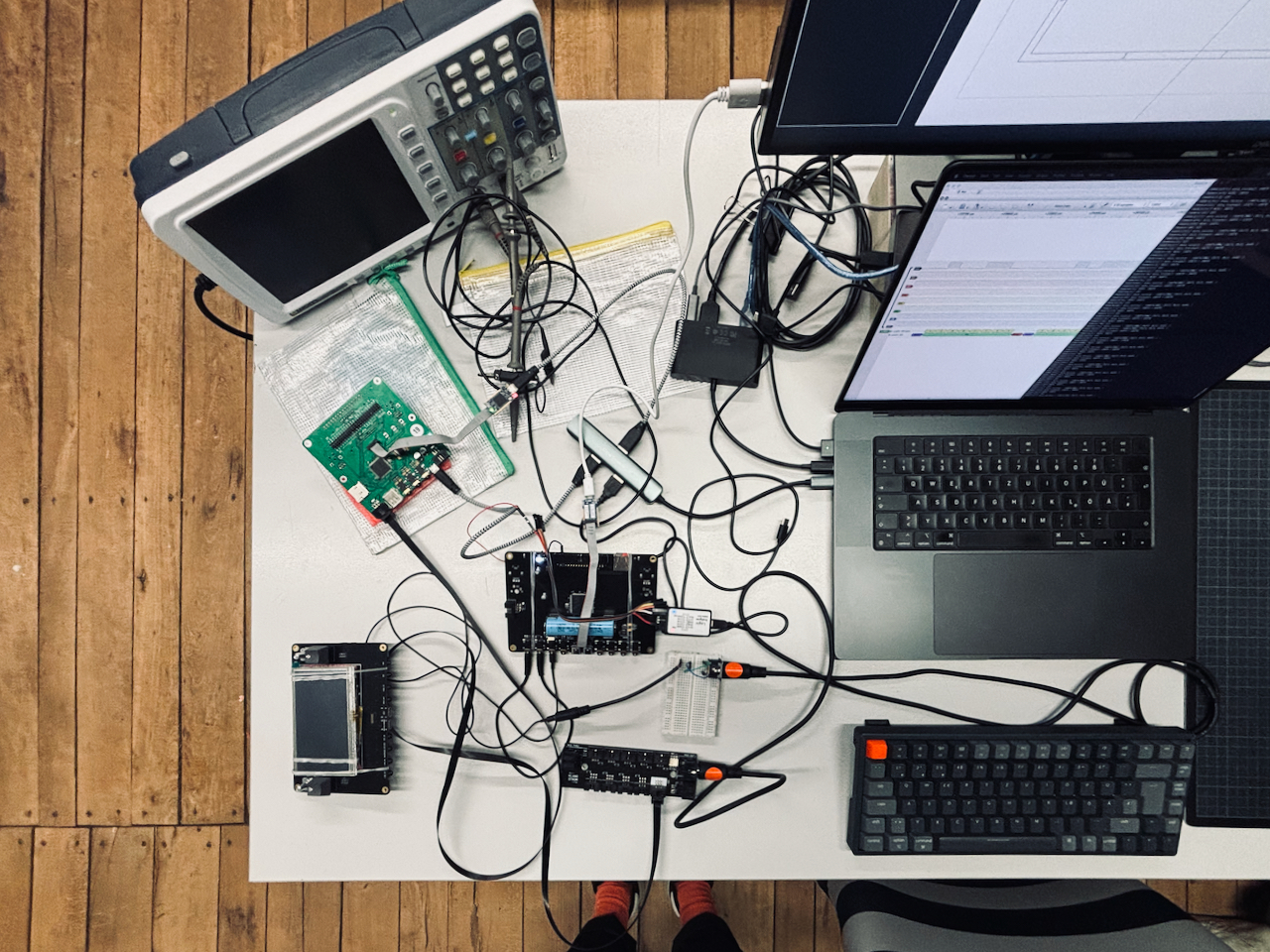
uiiuuiiiuiiih, this was much more complicated then anticipated. i went berserk after things did not function as expected and suddenly there were cables everywhere. but let s start at the beginning and end with happy ending. so the idea was to implement MIDI TRS1 connectors for input and output of analog ( or UART or serial port based MIDI ).
it turns out the world of MIDI via TRS is a mess. there are TYPE A, B and C connectors which differ in the way the 3 relevant pins of the old-style DIN-5 ( or DIN 41524 ) MIDI connector are mapped onto the 3 parts of the TRS connector. as it turns out since a few years TYPE A is the standard also accepted by the MIDI Association ( it is somewhat telling that every other link on midi.org on the topic produces a 404 ). this one however is informative: [UPDATED] HOW TO MAKE YOUR OWN 3.5MM MINI STEREO TRS-TO-MIDI 5 PIN DIN CABLES
i went for TYPE A of course.
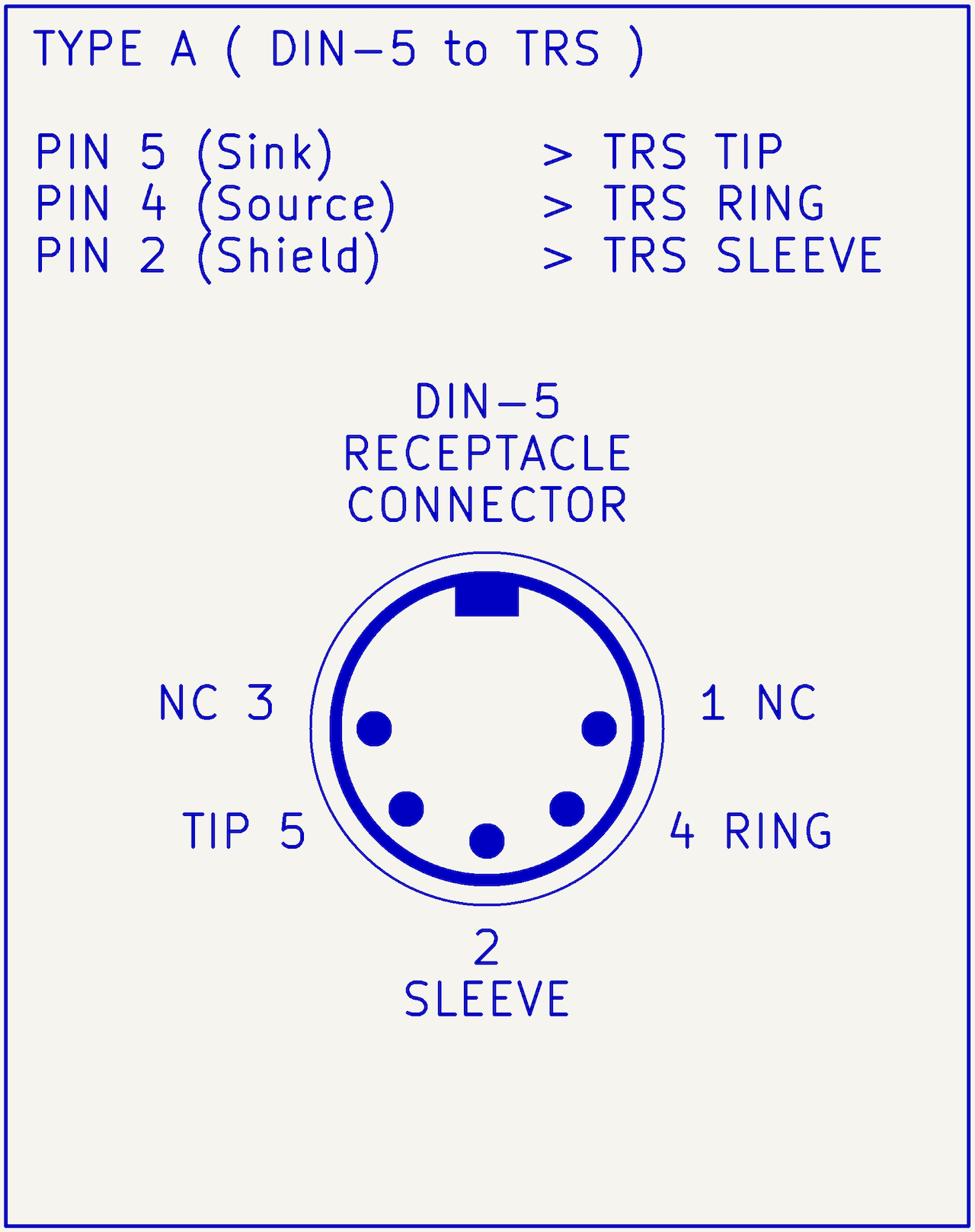 @image(looking into a TYPE A MIDI TRS receptacle connector2.)
i set the BAUD rate to 31250 and? nothing!
first, i really struggled with getting UART receive (RX) to work in HAL-based environment. i know everybody is hating on how crappy the HAL is. not me usually, but in this case i agree that it is somehow not well designed. it literally requires the application, when running in interrupt mode, to collect the incoming message byte-by-byte when the package length is unknown. essentially this took some time to find out and work with. i did, however, use this detour to implement and test UART via DMA which is faster nicer and the way to go anyway. after some digging it turned out that the magic commands are HAL_UARTEx_ReceiveToIdle_DMA which receives data until line goes idle, __HAL_DMA_DISABLE_IT which disables half-transfer callback as well as the callback function which gets called after receiving data HAL_UARTEx_RxEventCallback():
void HAL_UARTEx_RxEventCallback(UART_HandleTypeDef *huart, uint16_t Size) {
    // do something with data
    // restart RX
    HAL_StatusTypeDef status = HAL_UARTEx_ReceiveToIdle_DMA(&huart,
                                                            RX_DMA_buffer,
                                                            RX_DMA_BUFFER_SIZE);
    __HAL_DMA_DISABLE_IT(&hdma_uart_rx, DMA_IT_HT);
}
still, even after implementing UART with DMA i was struggling to get coherent data from KLST_SHEEP ( predecessor to KLST_PANDA ) to KLST_OCTOPUS ( UART-MIDI bridge ) to KLST_PANDA’s MIDI input. i finally got around to putting the logic analyzer to use3.
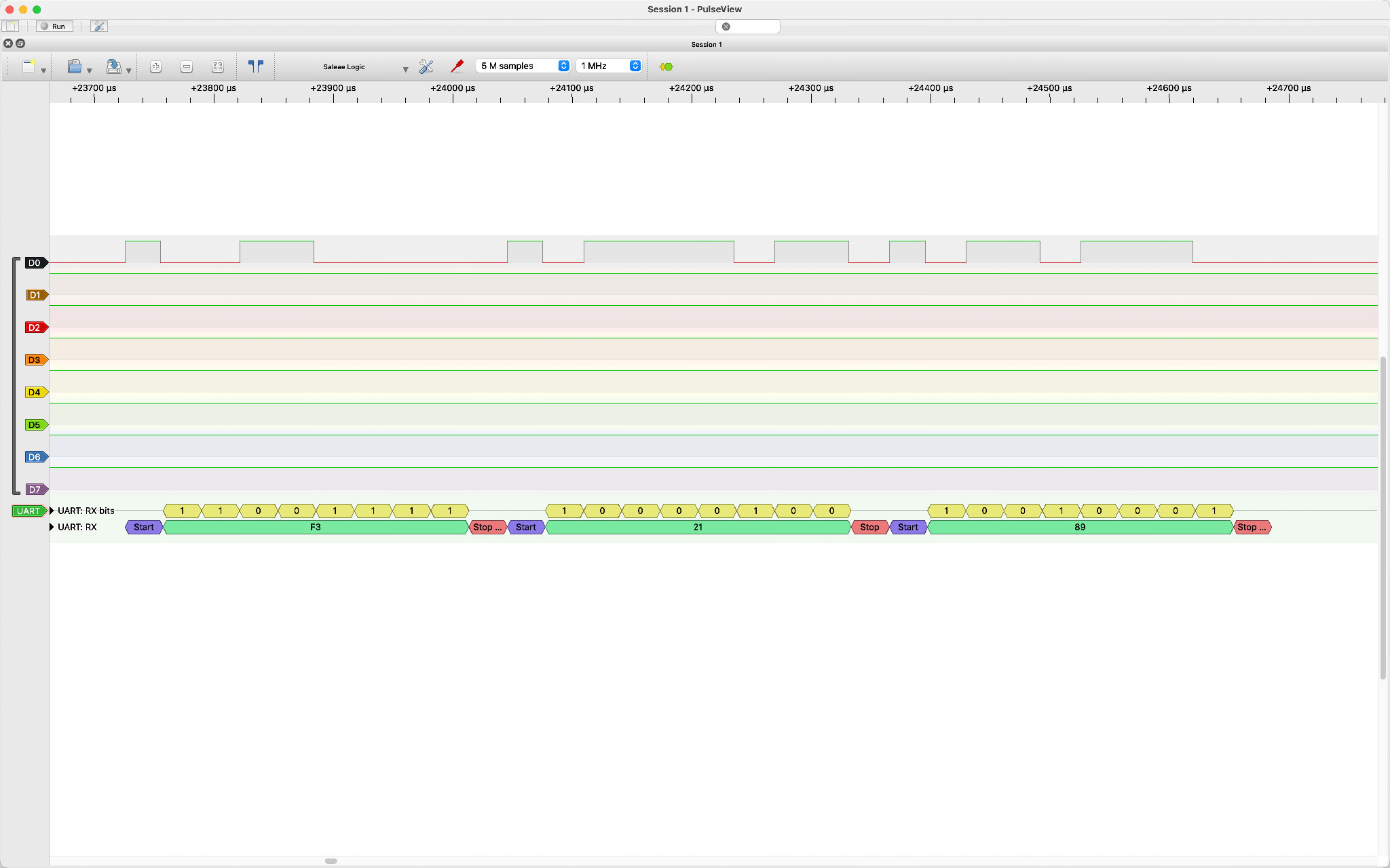
in sequence i started measuring the UART signal ( 0xF3, 0x21, 0x89 ) from KLST_SHEEP to KLST_PANDA and all the intermediate steps and sent:
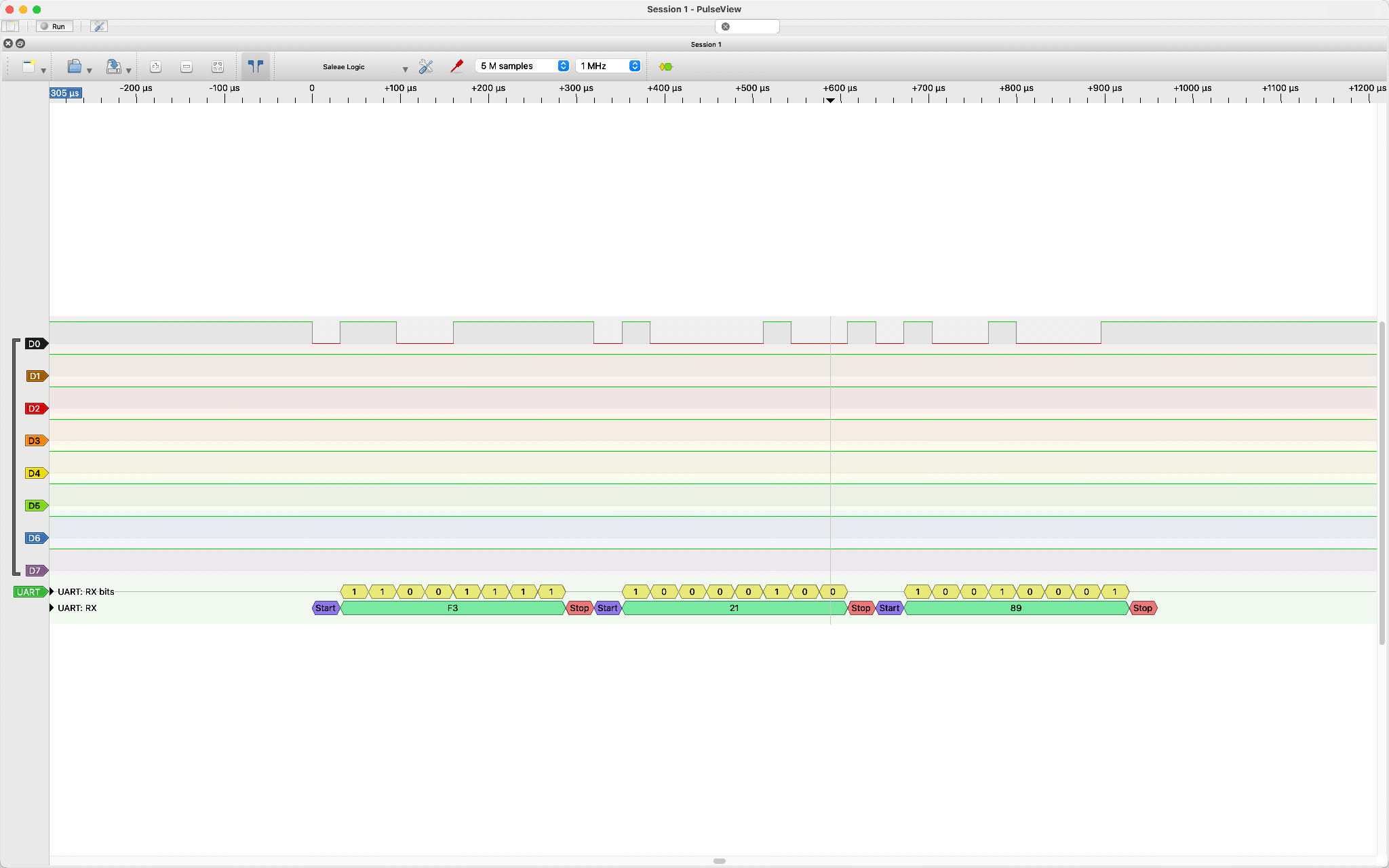
output directly from KLST_SHEEP UART. data is OK.
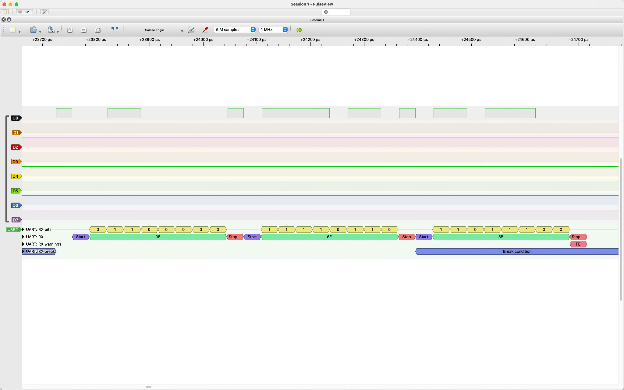
output at KLST_PANDA UART receive (RX) line right after the H11L1SR2M opto-coupler and voila: the signal is flipped and the transmitted data as a result corrupted. this becomes immediately obvious as UART has a default to high state i.e when there is no communication the data line is pulled high. in the image about it is pulled low ( left side of the screen ).
two things happened then: 1. i found out that the logic analyzer but also STM324 have features to invert the data line i.e KLST_PANDA received the proper bytes ( 0xF3, 0x21, 0x89 ) which made me happy as this meant that i could at least use the MIDI port like this. and 2. i realized that i had made a mistake when building my own MIDI TRS on a breadboard and had flipped SOURCE and SINK which essentially mimicked a TYPE B connector. once i corrected this issue i could set my UART data line back to normal and everything worked fine. i already tested with other equipment like the MIDI interface of Arturia MiniFuse 2. all good!
the nice things about this that i now know that KLST_PANDA is working and that, if need be, i could turn it into a TYPE B tolerant device just via software … nice.
-
TRS is an abbreviation for
Tas in tip,Ras in Ring andSas in sleeve. in this context it refers to a 3.5mm audio connector also known as audio jack. ↩ -
or buchse or socket. BTW as a visual designer i must really say that the electronics is struggling and still has not found a good way to talk about connectors and their respective pin numbers. are you looking into the connector or away from it? is this plug or pin or the receptacle ( not to mention the super weird nomenclature of male and female ) ↩
-
one of the lessons learned: have a logic analyzer on you at all times … from the beginning! ↩
-
in STM32CubeIDE it is an Advanced Feature found in the UART parameter setting and is called RX Pin Active Level Inversion. ↩