KLST_CATERPILLAR
KLST_CATERPILLAR is a reduced version of KLST_PANDA and should run on the same firmware ( minus some peripherals ). it hopefully solves the issues with the microphones as well as the audio codec and a few minor ones.
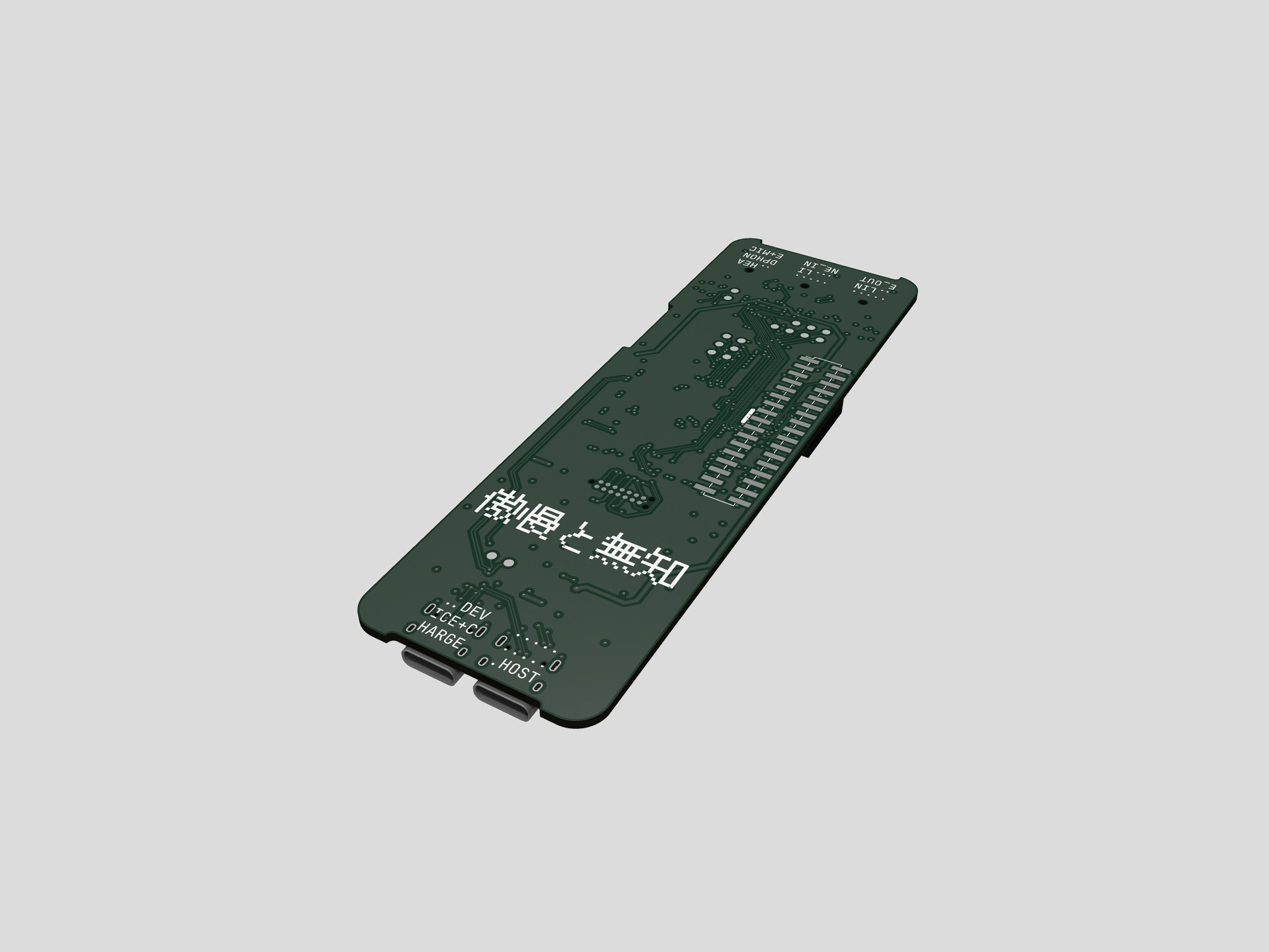
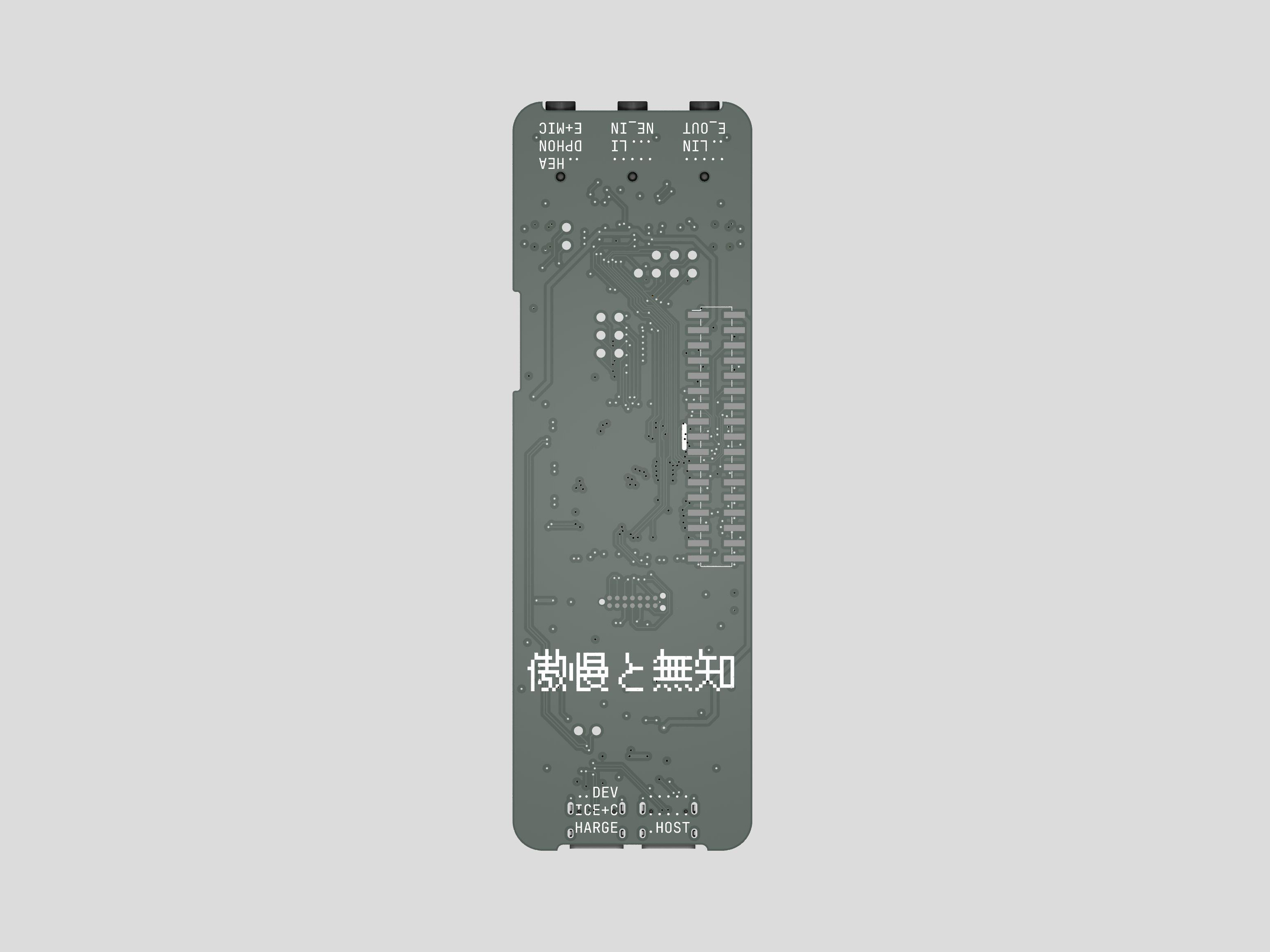
but most importantly i also added the cautionary characters 傲慢と無知 to the board. these are japanese and roughly translate to arrogance and ignorance. with this i want to remind myself ( and if interested also others ) to be less arrogant about my own skills and capabilities while at the same trying to be less ignorant to the things that might go wrong. one implementation of this is e.g to carefully add test points to a PCB where feasible.
and to take a bit of a more optimistic perspective on this affair: since a few months i started framing the KLST_PANDA project ( and essentially the entire KLST idea ) under the term of Subtractive Development Platform in order to emphasize the idea that KLST_PANDA is everything all at once1. so putting this idea to test, i was able to design and send out the KLST_CATERPILLAR board in approx 10h:
- started from KLST_PANDA design @date(2024-03-15 11:44) ( 6h )
- finished routing and positioning @date(09:30 2024-03-16) ( 2h )
- added GPIOs @date(23:30 2024-03-16) ( 1h )
- completed and ordered board @date(21:30 2024-03-17) ( 1h )
i ordered 10 fully assembled boards and including taxes, customs and shipping costs each board should cost around 35.00EUR. which is not super cheap but at such low quantities is ok-ish.
features
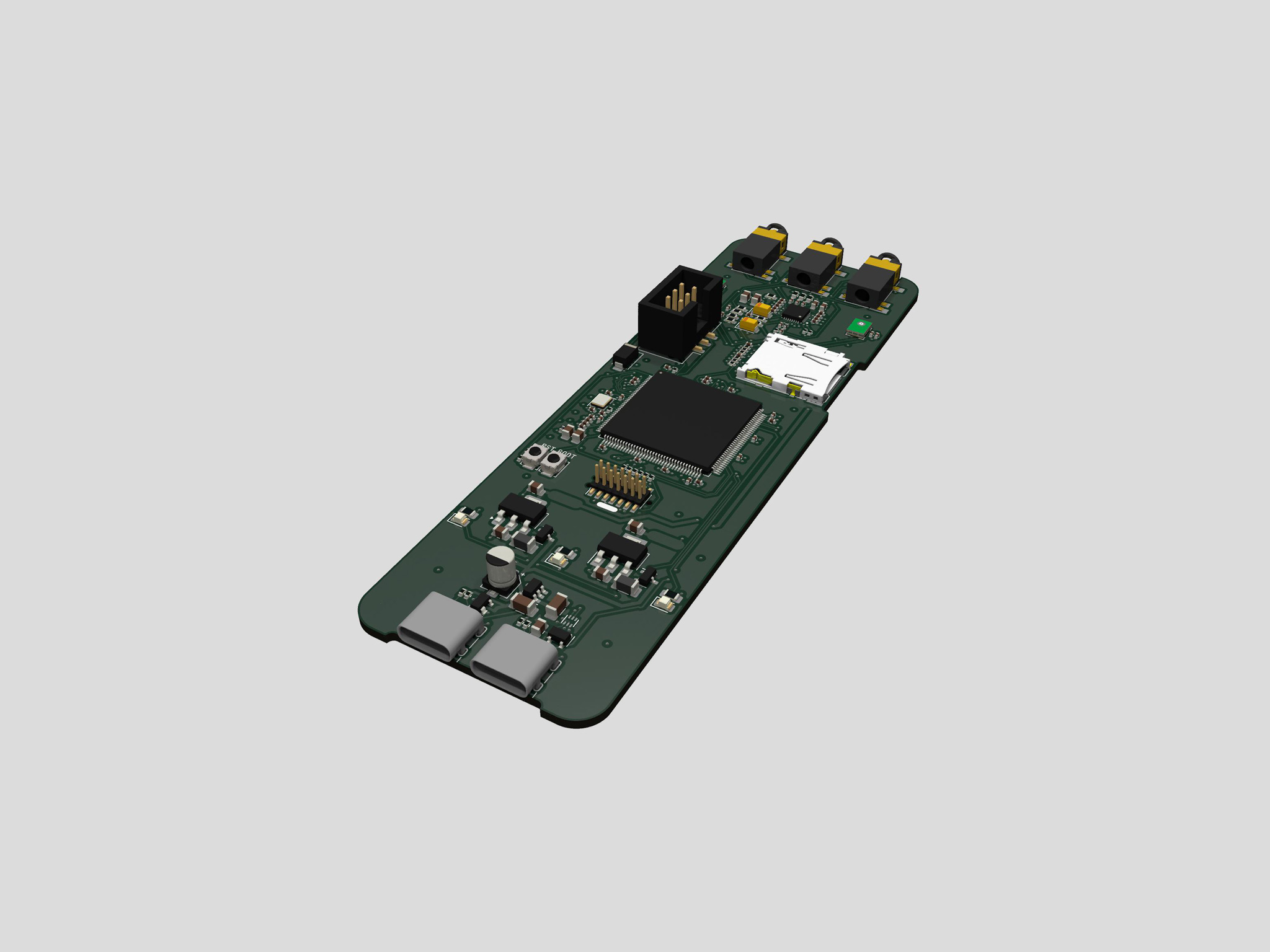
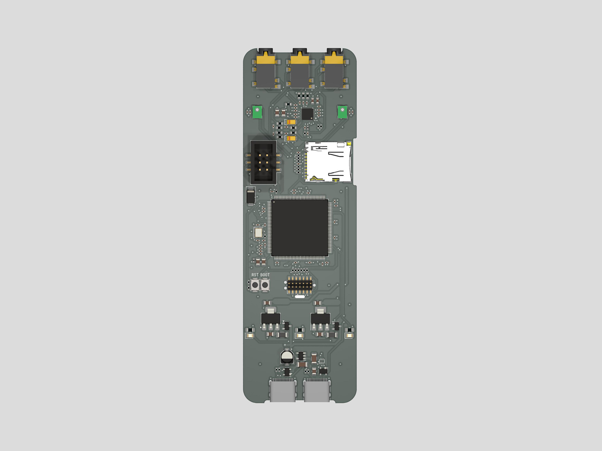
- MCU
STM32H723ZGT( 550MHz, 564KB RAM, 1024KB Flash Memory ) - audio codec
WM8904( stereo headphone amplifiers, mono microphone input, stereo line in and out ) - on-board microphone
MP34DT05TR-A( 2 MEMS on-board microphones ) - SD Card ( 4-bit wide SDMMC interface )
- USB device + host ( 2 USB-C connectors )
- GPIO ( 34-pin port with 28 General Purpose Inputs and Outputs and power supplies )
- IDC serial ( 6-pin shrouded IDC connector )
- programmer interface ( SWD STD14 connector and Tag-Connect TC2070-IDC-NL-050 footprint )
- Dimmable LEDs ( 2 user-programmable, dimmable ( via PWM ) white LEDs )
- Buttons ( RESET and BOOT_MODE buttons )
-
which is often a big challenge when designing a system with multiple components: each component works nicely when tested alone, but when put together some unexpected interaction between components starts to cause problems. ↩